Calibration And Testing Device For Tektronix And All Quality Oscilloscopes


PYRAMID GENERATOR USED TO CALIBRATE AND TEST TEKTRONIX AND OTHER HIGH QUALITY OSCILLOSCOPES. BRAND NEW -- CALIBRATED -- WARRANTED.
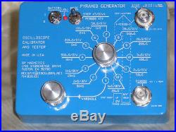
The Pyramid Generator (PG) is a self-contained, portable, battery operated, hand-held device very suitable for. Laboratory calibrating or field testing any high-quality digital or analog oscilloscope.
It features a crystal- controlled oscillator, a regulated power supply and, in the PERIOD position of the MODE switch, an amplitude and. Time duration controlled stair step output which looks like the vertical cross section of a ten layer Egyptian.
The PG features a variable period in selector switch position 1 and eleven calibrated PERIODs going from. 50 mS to 20 uS in steps of 1-2-5 sequence in the next eleven positions when the MODE switch is set to the PERIOD. Each Pyramid stair step consists of 20 steps total, 10 steps up and 10 steps down in the time frame of one PERIOD. The period signal is available at the PERIOD BNC on the front panel.The stair step counts up when the. PERIOD level is high and counts down when the PERIOD level is low.
The Pyramid output is amplitude-controlled at. 3V peak to peak into 1 M Ohm and 0.3V peak to peak into 50 Ohms. The PERIOD output is a 6V square wave (Zo=1K) and is used to test the external triggering capabilities of the.
Unit Under Test (UUT) and can also be used as a source of a selectable precision signal going from 50mS to 20uS. In either a 1-2-4 or 1-2-5 sequence depending on the setting of the MODE switch. In the PERIOD position of the MODE switch a 1-2-5 frequency division sequence is used. In the STEP position of the MODE switch a 1-2-4 frequency division sequence is used. The PG can be used to reliabily set vertical amplitude calibration, horizontal time calibration and to test.
Triggering capabilities at each of the ten steps up and the 10 steps down when the MODE switch is in the PERIOD. The PG is housed in a light blue powder-coated die-cast aluminum box measuring 4.5" X 3.5" X.
1.25 with solid aluminum knobs and bright white legends on the face. A BNC PERIOD output is provided which is.
High on the up-count and low on the down-count waveform of the Pyramid. The PG is powered by a single 9V battery. And uses an LED to alert the operator that the battery is getting low and that the generator will soon be out of. Calibration if the battery is not replaced. The low battery LED is flashed at power on for about 1 S.Battery life is in excess of 30 hours at normal room temperatures. An earlier purchaser of a PG, has been kind enough to prepare a YouTube demonstration of the PG. Can be accessed by clicking here to view the video. (note the two underscores between the Y and 8, these underscores may be masked by the underline if it is present).
Of Oxford Michigan has also been kind enough to prepare a YouTube demon- stration of the PG in action. Both presenters cover the operation of the PG using calibrated analog and digital oscilloscopes in a most complete. HISTORY BEHIND THE PYRAMID GENERATOR. I once attended the bi-monthly electronics swap meet in Santa Ana, CA. There was an out-of-state vendor there who. Had a number of Tektronix 475A and 485 oscilloscopes that were very reasonably priced. The vendor assured me that. All of these oscilloscopes were in working order; however, there was no power available to verify this statement.I accepted this explanation and after several minutes of intense haggling we arrived at a mutually agreeable price. And then I was the proud owner of four 485 and three 475A Tektronix oscilloscopes. During the next week I fired. Them up and found that only two of the 475A's and none of the 485's had a trace visible on them.
One of the 485's. Was lacking the inverter board and as well had no tunnel diodes nor any of the socketed ICs.Needless to say, I was. I decided that I needed.
A portable calibration tester or a very long extension cord. I do not design extension cords but I do design portable. Testers-the Pyramid Generator is the culmination of that effort. In the PERIOD position of the MODE switch there are eleven Pyramid crystal-controlled PERIODs, 50mS, 20mS, 10 mS.
5mS, 2mS, 1mS, 500uS, 200uS, 100uS, 50uS and 20uS. In the STEP position of the MODE switch there are eleven Pyramid crystal-controlled STEPs, 2mS/DIV, 1mS/DIV. 500uS/DIV, 200uS/DIV, 100uS/DIV, 50uS/DIV, 20uS/DIV, 10uS/DIV, 5uS/DIV, 2uS/DIV, 1uS/DIV. One potentiometer controlled switch setting with variable periods from 100mS to 5mS. Low battery warning LED on front panel. PYRAMID OUTPUT BNC waveform is 3V P-P into 1 MO and 0.3V P-P into 50 Ohms.Accuracy is +/- 2% into 50 Ohms. Crystal-controlled PERIOD and STEP accuracy is +/-50 PPM (Parts Per Million) or +/. Regulated power supply used to stabilize output amplitude. PERIOD BNC output provided to allow external triggering checks. Waveform is high on up count, low on down count.
Single 9 Volt alkaline battery powers the PG. Battery life, under highest frequency output and fresh battery, is in excess of 30 hours. Housed in die-cast aluminum case with light blue powder-coated exterior, bright white legends and solid. Please write me for any additional information you may desire. Each PG comes with a free extensive manual which covers the usage, care, calibration and feeding of the device. You would like a copy of this manual for your self then write me to get your free. You will not be besieged by endless e-mails professing the merits of the PG. You will get one note from me and. That will be the attached manual. The MODE switch is incorporated because the 2 to 5 transition on the UUT is not divisible by 2, it is divisible by. A factor of 2.5. The internal electronics is modified using the MODE switch to overcome this problem. You are in switch position 4 viewing a 10 mS Pyramid PERIOD with the UUT in 1mS/DIV and the MODE switch in the STEP. When you advance to position 5, the 5mS Pyramid PERIOD, and advance the TIME/DIV control on the UUT to.500uS/DIV you will see that the Pyramid Period is 4mS. Operating the MODE switch to the PERIOD position will bring.
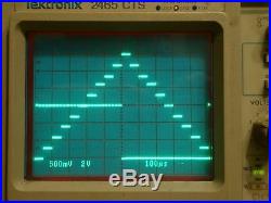
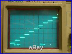
The period to the full 5mS. If you want to view the Pyramid Period switch the MODE switch to PERIOD, the frequency division ratio will be 1-2-5. If you want to view the individual Pyramid steps, switch the MODE switch to STEP, the frequency division ratio. The display shows two pictures of the output of the PG. The one with the full 20 steps also has the PERIOD waveform. Shown on the lower portion of the picture and the TIME/DIV setting on the oscilloscope is set at 100uS/DIV. Oscilloscope is being triggered on the PERIOD input. You will note that the PERIOD waveform is high when the STEP.Count is going up and the PERIOD waveform is low while the STEP count is going down. There are 20 steps total, 10. Up steps and 10 down steps, each step is 50uS so 20 steps would be 1000uS or 1mS. This is correct as the horizontal.
Time is 100uS/DIV times 10 DIV for a total of 1000uS or 1mS. The single waveform picture shows 10 steps up at 50uS/DIV. The PG is set to position 7 (50uS/DIV) and the MODE. Switch is in the STEP position. The 50uS/DIV steps show clearly the accurate step transition at each vertical. This setting is the best one to use while calibrating the horizontal time base on an oscilloscope.The front panel of the PG portrays the relationship between the STEP and Period wave forms. Dotted lines are used to. Illustrate the relationship between the PERIOD and STEP wave forms.
When the MODE switch is in the up or STEP position the STEP signal is available at the upper BNC and the upper labels. On the rotary selector switch are applicable. When the MODE switch is in the down or PERIOD position the lower BNC has the PERIOD signal and the lower labels on. Each position of the selector switch are applicable.
The STEP and PERIOD signals are always available irrespective of the position of the MODE switch. The 1-2-4 or the 1-2-5 division is not a problem when the operator is aware of the signal desired and the position. The PG has a 10 step up and 10 step down PYRAMID OUTPUT waveform measuring 3 Volts peak-to-peak into 1 M. Ohm and 0.3 Volts peak-to-peak into 50 Ohms. Each step on the Pyramid will be approximately 30 mV.
Amplitude change is not controlled and is not linear. When the UUT input is terminated into 50 Ohms the peak-to-peak. Pyramid step will be 300 mV. The output impedance of the PYRAMID OUTPUT signal is 450 Ohms, +/- 1%. The STEP duration and the Pyramid PERIOD table is as follows.Pyramid Generator Outputs Versus Switch Position. MODE Switch In PERIOD Position. The PERIOD signal is also available as a precision time controlled standard. The PERIOD signal has a 1K series.
Resistor in the output to protect the integrity of the internal electronics. This 1K resistor may be used as a. Dropping device when a Zener diode of a required value is connected to ground to clip the signal at the voltage. Value of the Zener diode.PERIOD Outputs Versus Switch Position. MODE Switch In STEP Position.
Each 1-2-4 PERIOD duration is. Each 1-2-5 PERIOD duration is. The PG can be used to test the UUT's ability to trigger on each step of the Pyramid waveform by slowly advancing. The UUT trigger level and changing the UUT trigger slope from + to. The UUT should be able to trigger on the start. Of the Pyramid steps and progressively the Triggering Level control is rotated. THREE TEST SETUPS USING THE PG. I will detail three test setups and describe what you can learn from each setup. 1 TRIGGERING Connect the STEP OUTPUT to the vertical input on the UUT. Trigger the UUT internally and obtain a stable display. Slowly rotate the UUT TRIG LEVEL control CW and CCW. Change the UUT TRIGgering SLOPE from positive to negative and. Watch the display as you rotate the TRIG LEVEL. If the triggering is working properly you should be able to see the. UUT trigger on successively higher or lower levels of the PG waveform as the TRIG LEVEL and SLOPE controls are rotated.2 VERTICAL AMPLITUDE Connect the STEP OUTPUT to the vertical input of the UUT, connect the PERIOD output to the EXTernal TRIGger input on. Obtain a stable signal with one full cycle of 20 stair steps. Adjust the VERT POSition control so the very. Bottom of the PG waveform is on a lower graticule line.
Adjust the UUT internal vertical gain control to obtain. Exactly 3 Volts peak-to-peak waveform on the UUT screen. You have now calibrated the vertical deflection on the UUT.
3 HORIZONTAL LINEARITY Obtain a stable display as in 2 above. Again, trigger on the PG PERIOD output.
Operate the PG's MODE switch to. Rotate the UUT V/DIV control to see 10 steps from the PG on the UUT. Adjust the internal horizontal gain. Potentiometer inside the UUT to obtain a step at each vertical graticule mark. You have now calibrated the horizontal.It is a good idea to check each setting of the TIME/DIV switch on the UUT against the output of. Doing this will confirm that the precision resistors and capacitors forming the UUT time constants are. Please write me to get or clarify information on the PG test setups. FREQUENCY LIMITATIONS OF THE OUTPUT WAVEFORM.
The D2A (Digital 2 Analog) converter portion of the PYRAMID OUTPUT uses a counter. When the input frequency is. High, noticeable switching spikes and rounding of the STEP corners is apparent when the output load is 1 M Ohm. Device is perfectly usable at this level, it is just not too pretty.
For that reason I have down graded the. Amplitude fidelity at the higher frequencies when the load is 1 M Ohm.
To see a cleaner waveform terminate the oscilloscope's input in 50 Ohms. Of mistreatment of the unit. This includes damage to the case or hardware, corroded battery contacts or other. If you are not in the CONUS please send me a note. UUT 50 Ohms Input Impedance.UUT 1 MO Input Impedance. +/- 3% on Selector Switch ranges 1 to 9.
+/-5% on Selector Switch ranges above 9. STEP output with MODE Switch in PERIOD position. PERIOD output with MODE Switch in PERIOD position. +/- 50 PPM on all ranges. Connects the battery to the electronics.
No standby current is drawn in the 0 position. Warns the operator that the battery voltage is falling below 8V and that the unit will soon be out of calibration. LED flashes for 1 S upon power on. Used to modify the internal electronics such that the 1-2-5 sequence is maintained in the PERIOD position and a 1-2-4 sequence in the STEP position in both the STEP and PERIOD position of the MODE switch. A 6 Volt square wave used to test the external triggering capabilities of the UUT.
Output is high on the count up portion of the Pyramid waveform and low on the down count portion. Rise and fall times are about 100nS. The Pyramid waveform output BNC. A twelve position switch used to select the output waveform frequency.Used only in position 1 of the selector switch to vary the output waveform PERIOD. The Pyramid Generator is housed in a Hammond 1590BB die-cast aluminum enclosure measuring 4.5" X 3.5" X 1.25.
A die-cast bottom lid is held in place with four Phillips head stainless steel screws. The Pyramid Generator case and base plate are powder coated a light blue non-metallic finish with bright white legends on the front panel.
Bright finish matching solid aluminum knobs are used on the front panel. Four stick-on feet are provided. The Pyramid Generator uses one standard alkaline 9 Volt battery held in place by a sturdy metal clip. Battery replacement requires removal of four Phillips flat head screws on the bottom lid. No standby current is drawn when the BATTERY switch is in the 0 position. The Pyramid Generator weighs under 1 pound with battery installed.Congratulations, you made it to THE END. The item "CALIBRATION AND TESTING DEVICE FOR TEKTRONIX AND ALL QUALITY OSCILLOSCOPES" is in sale since Saturday, October 13, 2018.
This item is in the category "Business & Industrial\Test, Measurement & Inspection\Testers & Calibrators\Calibrators\Other Calibrators". The seller is "reed-d" and is located in Tustin, California. This item can be shipped worldwide.- Country of Manufacture: United States
- Non-Domestic Product: No
- Modified Item: No
- Country/Region of Manufacture: United States
- Custom Bundle: No
- Brand: Pyramid Generator
